Marine and Offshore removal planning
Shell-and-Plate Heat Exchangers Removal for Marine and Offshore Facilities
Prepare a removal and logistics review for shell-and-plate heat exchangers installed at a marine or offshore operation. The process begins with isolation, residual-service, dimensions, weight, access, lift, loading, and responsibility facts—not a guaranteed pickup date.
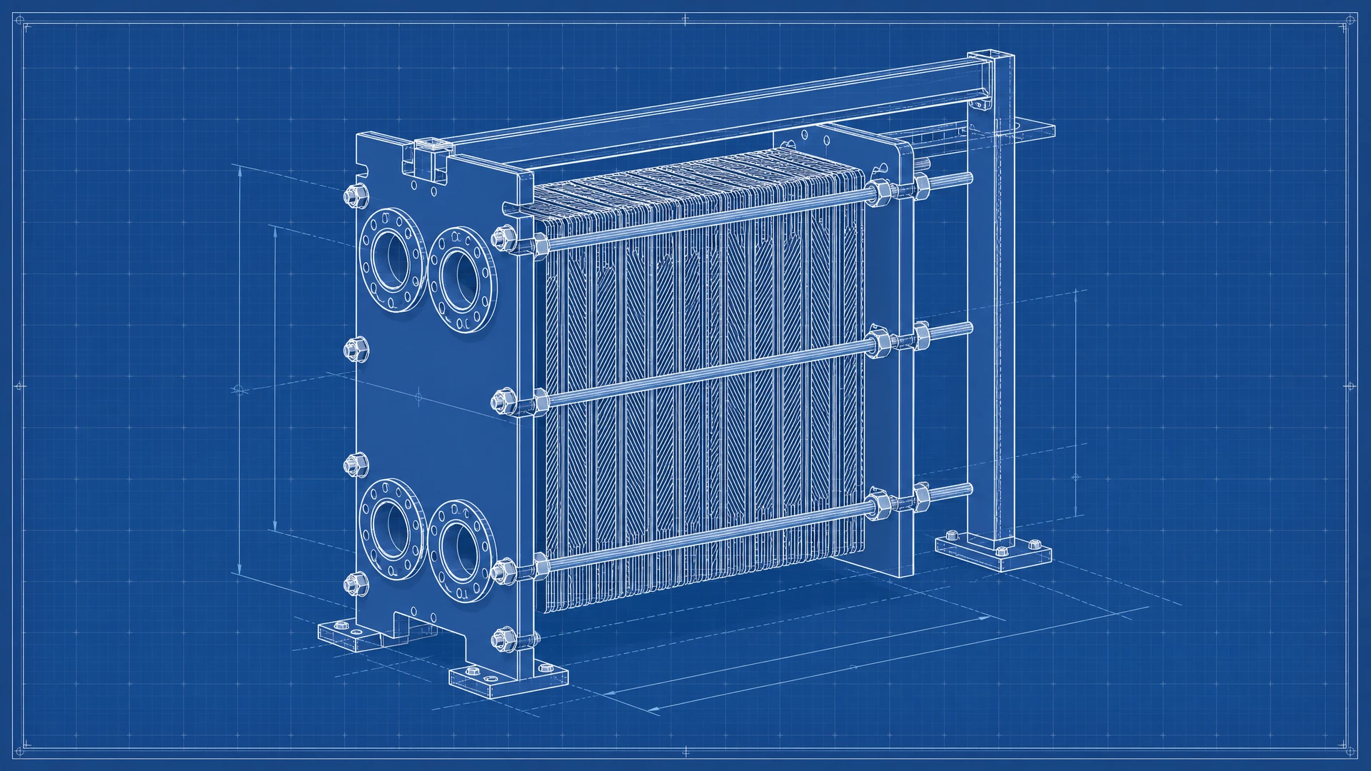
Shell-and-Plate Heat Exchangers removal context in Marine and Offshore
Shell-and-plate heat exchangers combine the high pressure and temperature capabilities of shell-and-tube designs with the compact, high-efficiency heat transfer of plate-and-frame designs. Installed removal from a marine or offshore operation also depends on the actual process, residual service, isolation status, surrounding systems, and facility access described in the marine and offshore evidence record.
The removal plan must be based on the submitted unit and site. This page does not imply a local crew, permit authority, preapproved lift, guaranteed pickup, or unconditional service availability.
Isolation and residual-service record
Before commercial or logistics commitments, document how both exchanger sides were isolated, drained, cleaned, released, and separated from the marine and offshore system. Unknown conditions should be identified as unknown.
- Check for material certifications (e.g., Titanium, Duplex stainless steel).
- Verify marine class approvals (ABS, DNV).
- Inspect for signs of pitting or crevice corrosion.
- Drain and purge all fluids/refrigerants prior to removal.
- cap and seal all connection ports to prevent contamination.
- use proper lifting equipment suitable for heavy metallic construction.
Dismantling, loading, and freight planning
The physical plan should connect the shell-and-plate heat exchangers configuration to verified dimensions, weight, lifting points, access, staging, carrier profile, and responsibility boundaries.
- Drain and purge all fluids/refrigerants prior to removal.
- cap and seal all connection ports to prevent contamination.
- use proper lifting equipment suitable for heavy metallic construction.
- ensure clear access for extraction without damaging the outer shell.
- Ensure isolation from seawater intake and process fluid loops.
- Drain and flush residual brine or cooling media.
- Account for tight space constraints and weight limits on offshore platforms.
Written scope before work
Dismantling, rigging, loading, freight, scheduling, and payment are conditional project functions. A written scope must identify responsible parties, safety release, access rules, exclusions, equipment boundaries, carrier requirements, and commercial terms before performance.
Shell-and-Plate Heat Exchangers Removal for Marine and Offshore Facilities condition and logistics record
For shell-and-plate heat exchangers removal for marine and offshore facilities, record observable condition, installation state, dimensions, weight, current location, site access, loading capability, and timing constraints before requesting commercial review.
Page-specific questions
Frequently asked questions
Can removal of shell-and-plate heat exchangers from a marine and offshore facility be included?
It may be considered after written review of isolation, residual service, dimensions, weight, access, lifting, dismantling, loading, safety, schedule, and responsibility boundaries.
Is pickup or removal guaranteed?
No. Submission requests review only. Removal, loading, freight, timing, payment, and provider scope require separate written confirmation.
What site information is needed?
Provide installed and access-route photos, elevation and opening dimensions, verified weight, lifting-point information, isolation and cleaning status, site rules, staging conditions, loading capability, and schedule constraints.
Technical references
Secure equipment submission
Request a review for this heat exchanger
Required fields are marked. Share the equipment, condition, location, access, and supporting records available for review.